autocad 3d modeling change drawing plane
Create a 3D Site Plan Using CADMapper and AutoCAD
Demand to speedily create a 3D site plan in AutoCAD?
Hither's how to exercise it.
This tutorial covers the following information:
-
Setting up a 3D site in CADMapper
-
Converting Units: Metric to Imperial
-
External References: Separating Layers into Drawings
Disclosure:
CADMapper is a website that can relieve architects, designers, and planners tons of fourth dimension by automatically generating 3-Dimensional information for over 200 cities around the world. CADMapper generates 3D models that can be used with AutoCAD, Sketchup, Rhino, and Illustrator. To generate information for topography, buildings, and streets, CADMapper pulls information from OpenStreetMap.
I should commencement by saying that my design work primarily involves the schematic design stage of architectural blueprint. I understand that site data should be field-verified by professionals in surveying, civil engineering, etc. to ensure accurateness. The intention of this tutorial is to utilize CADMapper to create a basis for architectural schematic designs.
Setting upward a 3D site in CADMapper
Stride ane: Observe your site - Start with Google Maps.

I like to kickoff by finding my site in Google Maps. Ofttimes, in that location is little information given that specifies coordinates or a concrete address of a site. Searching for the site in Google Maps gives me a better understanding of what my site looks like from an aerial perspective.
Once you notice your site in Google Maps, caput over to CADMapper.com and blazon in the judge address - or ii intersecting streets.
CADMapper only provides vector line information, and so it might be cumbersome to try to search for your site starting in CADMapper. Look between Google Maps and CADMapper to strop in on your site, and create a box in CADMapper that captures the information you lot need from your site. CADMapper is complimentary, but up to 1km of information.
E'er try to capture more information than you call up y'all need. You lot never know when you might need the information in the hereafter. Information technology's better to have information technology and non need it, than to need it and not have it - I've had to stitch multiple CADMapper files together earlier because I left out some important information when I created my initial file, and it's a real hurting to go through that process.
Step two: Plow on 3D Buildings

If y'all desire building height information, bank check the box for 3D Buildings. If edifice information is available (which it oftentimes is in large cities), CADMapper volition create mesh geometry of buildings in the CAD file. You can specify "Simulated Elevation Information", in which CADMapper will generate buildings without meridian information to a value that you specify. Non a necessary step, but it can you salvage drawing time.
Step 3: Select 3D Topography, topography contours spaced at iv meters.

It's expert do to just collect equally much information as we can go, early on in a project. The lowest spacing that CADMapper will generate for contour lines is four meters, which should be plenty of information to get you started in your pattern.
Step 4: Road Geometry, Select "Outlines"

CADMapper provides options for generating road graphics. Roads tin can exist depicted as single eye-lines, outlines, or mesh surfaces. If y'all intend on using this site file for fabrication, such as 3D printing or light amplification by stimulated emission of radiation-cutting, I would suggest choosing an pick that best suits your needs. For this tutorial, selecting "Outlines" will provide graphic separation between types of roads, and allow easy scaling of the drawing in AutoCAD. Additionally, "Outlines" is a practiced option to choose for laser-cutting site models.
Modify the road dimensions to specific dimensions: I recommend the following:
-
Highways: x meters
-
Major Roads: 8 meters
-
Pocket-sized Roads: half dozen meters
-
Paths: 4 meters
Step 5: Generate the CADMapper File

If everything is set to your liking, click on "Create File". It volition take a moment to generate the file.
Once the file is generated, you tin can examine the map in 3 views:
-
3D Axonometric View
-
second View
-
Topography
At this indicate, select download. The file will download as a unmarried .zip, containing one .dxf file that you can open up with AutoCAD.
Converting Units - Metric to Imperial
By default, CADMapper exports units in meters. For our purposes, nosotros need to convert meters to feet.'

Step ane: In the "Units" Carte, Change 'Decimal' to 'Architectural'
Type in command, "United nations" to open up the Units bill of fare. Change 'Decimal' to 'Architectural', and 'Millimeters' to 'Inches', respectively. Note that but changing the units volition not change the scale the drawing. For example, ii meters will exist converted to ii feet, which is wrong.
And so, we'll need to scale the drawing subsequently changing the units from metric to imperial.

Footstep 2: Verify the Altitude of a Road
Use the command "DIST" to measure the distance of one of the roads generated by the CADMapper file. It should read as i of the measurements that was specified on the CADMapper website. For this example, the road is half dozen meters.
Step three: Calibration the Drawing
If the road distance is 6 meters, information technology will need to exist scaled to 19.685 feet (considering 1 meter = 3.28084 feet) after changing the Units from metric to imperial.
Depict a polyline (command "PL") off to the side of your drawing in model infinite somewhere. Below that six meter line, draw a line of altitude, 19.685.
Use command "AL" for 'Marshal', and select EVERYTHING in model space. Deselect the (xix.685) line. We desire to scale everything in the cartoon except that line.

Select the first point of the (six units) line, and the outset bespeak of the (nineteen.685 units) line. And then, select the 2d betoken of the (half dozen units) line, and the second betoken of the (xix.685 units) line.
When prompted to 'Scale', select Yep.
If washed correctly, all of the elements in the cartoon will take scaled with the (6 units) line, which now matches the distance of nineteen.685. And so at present, when the Units are set to "Architectural" and "Inches", all of the roads should read as the equivalent majestic measurement.
External References: Separating Layers into Drawings

CADMapper conveniently sorts drawings elements into carve up layers. This is useful in terms of organisation, nevertheless, we should gear up our drawings in a way that allows multiple people to work on them. This may not be necessary for your detail projection, but information technology's proficient practice to learn the conventions of creating external references to keep file systems organized, and to allow the potential for multiple people to work on a single project.
Streamlined file systems = saved fourth dimension on drafting work. And saving drafting time volition open up time for more important stuff, like designing!
Here's how to quickly create external references from layers:
Step 1: Open the Layer Card


Type "LA" to open up the Layer Menu. Freeze all layers, so unfreeze the first layer that you desire to convert into an external reference. In this case, we'll offset the the layer called "buildings".
Next, type "Select" and "All" to select everything on that layer.
"Copy Base" with, CRTL+SHIFT+C, and so specify the origin indicate as 0,0,0 (x,y,z, respectively).
This is important, because copying the information with the origin signal will allow you to bring all of the drawings into the new "Chief Drawing" at the same point. This will ensure that the drawings are lined upwards correctly, maintaining accuracy in the information.
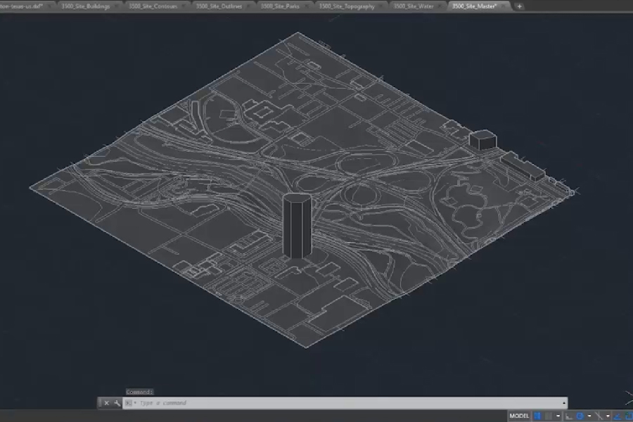
Step two: Create the "Master Cartoon"
Open a new drawing. This will go the "Principal Drawing", which will hold all of the xrefs that nosotros will be creating for each layer. The "Principal Drawing" will look exactly like the original file containing all of the private layer information. The benefit of setting up a master drawing this way, is that multiple people can work on individual files inside ane project.
For instance, 1 person can work on the "Buildings" layer. Another person can piece of work on the "Roads" layer, and then on.
This is not merely convenient for grouping drafting projects, merely information technology volition aid you build a consistent file organization that can exist applied to a number of different programs exterior of AutoCAD. Information technology's simply a system of file linkage, and these types of systems offering the most flexibility for organization, and drafting workflows.
One final annotation: the "Primary Drawing" should serve as a file for reference, and should not be fatigued on or referenced to other drawings. Changes made on all of the other external references volition reflect on the Master Drawing, however, changes made on the Master Drawing will not reverberate on the linked external references. It's a ane-way street, and maintaining this system will ensure that your project is clean and organized.
Expert luck!
You might also like…
mccleskeypreseved.blogspot.com
Source: https://rascoh.studio/blog/3d-site-plan-cadmapper-autocad-tutorial
0 Response to "autocad 3d modeling change drawing plane"
Post a Comment